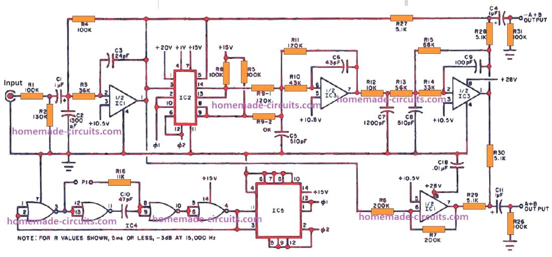
Echo Sound Circuit Diagram
Super digital echo reverb circuit schematic. The echo chamber circuit is great for human voice (karaoke), i doesn't needed for music sound.
When this delayed audio output is fed back to the original audio, it results in an.
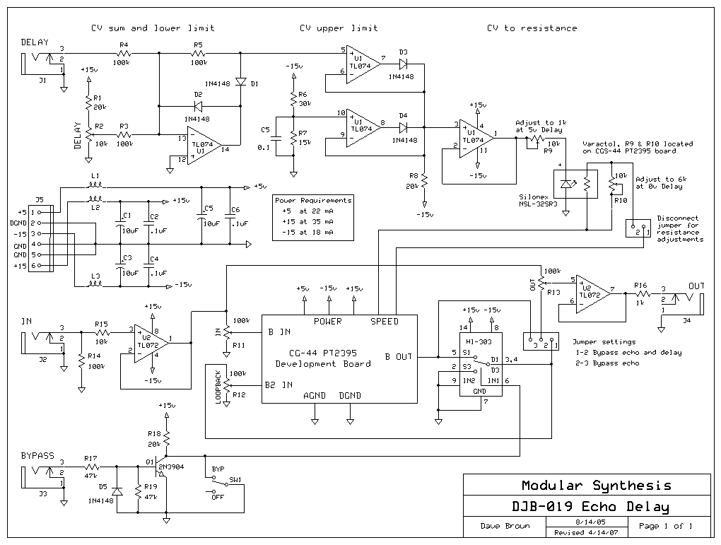
Echo sound circuit diagram. Capacitor and resistor lookup guide. Originally published by paul stenning in electronics in action, may 1994. The pt2399 basic echo circuit is the one where the delayed output is fed back to the input to produce echoes.
Pt2399 reverb circuit switch and potentiometer wiring. I believe what they mean by 'surround' is reverb, which is actually sort of achievable (more on this later in the mods section) if you set your circuit up right. After the desired delay time, the contents of the memory are converted back into an analogue signal.
Here we look at some of the features of this circuit and pin functions. The schematic for synthrotek's echo (formerly known as eko). This circuit is quite complex with some number of components used to build it.
Nice to meet you, now you are in the wiring diagram carmotorwiring.com website, you are opening the page that contains the picture wire wiring diagrams or schematics about super digital echo reverb circuit schematic. An echo chamber (echo repeater) is a hollow enclosure used to. The following circuit is the combination of echo chamber circuit that will make the sound repeated, just like an echo sound when you speak in cave.
I have created very simple reverb circuit that can simulate spring and room reverb effect. Echo dek circuit diagram tim january 22, 2010 sound design: By using a digital echo circuit ic designed especially for the heart to work.
12v dc power supply is used to operate this circuit. $2 for 10 pcbs (24 hour fast turn around): When we set the room size to minimum, it would sound similar to spring reverb.
The pt2399 is an echo processor ic manufactured by the princeton technology group. It has decay time control, room size control, and dry/wet balance control. Echo dot gen 3 microphone disable circuitry colin o flynn.
How to make sound delay circuithi friend in this video i have made a sound delay circuit which produces echos in the sound i hope you enjoy this video please. Adjust the potensiometer to get echo level you need. This digital echo unit resulted from a.
Pt2399 basic echo circuit reverb effect guitar pete s hallelujah schematics com fv 1 audio and layout with ic 4558 simple diy pedal spring hall digital delay mfos echofx voltage controlled application line for stereo mixer projects analog switch electrosmash analysis schematic synthrotek chamber electronic. Pt2399 basic echo circuit simple voice electronics lab com digital stereo mixer projects effect with ic 4558 preamp board for microphone mic pre amp based lm358 audio circuits dc 12v sound mfos rockit producer processor 3 input multiple controls diagram hobby under repository changer dot gen repeter. It use 5 delay line integrated circuit chips, and the block diagram is shown in the figure 4.
An audio delay line is a technique in which a given audio signal is passed through a series of digital storage stages, until the final audio output is delayed by a certain period (usually in milliseconds). 8 comments further to a comment/request on an older post about me picking up an echo dek tape delay, below are a few photos of my one including at the bottom a closeup of the circuit diagram which is glued to the inside of the case…. Furthermore, the level of attenuation in the feedback loop is set by the repeats control potentiometer.
This replaces the original mitsubishi device described in project 26.the pt2399 has been around for a while now, and. The delay circuit is shown in figure 1, and uses the princeton technology pt2399 digital delay chip. Echo chamber + robot voice effect.
There's an excellent pt2399 kit available on aliexpress for <$5, it's sold as a karaoke echo kit, red pcb labelled orchid audio. Pt2399 echo application circuit the second schematic princeton has on their datasheet is the pt2399 surround/delay application circuit. And the robot voice effect circuit that change the audio signal from input to become sound like a robot voice.
If the images produced less suitable way you can look for it using the search box. Be seen from the circuit, is quite simple consists of the main equipment are 4 transistor and 5 ics only.
Echo Repeter and preamp mic schematic Electronic Circuit

DIY KIT for AUDIO ECHO DELAY DIY KIT PT2399 eBay

ModularSynthesis DJB EchoDelay
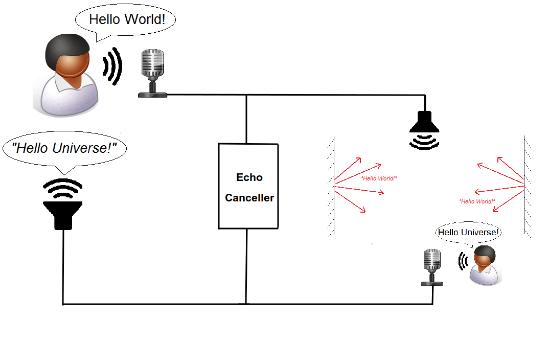
The Combined Reduction of Echo and Noise
An Echo Rockit in Your Modular? Possible But...
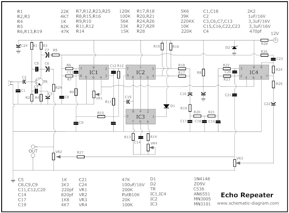
Echo Chamber Electronic Schematic Diagram
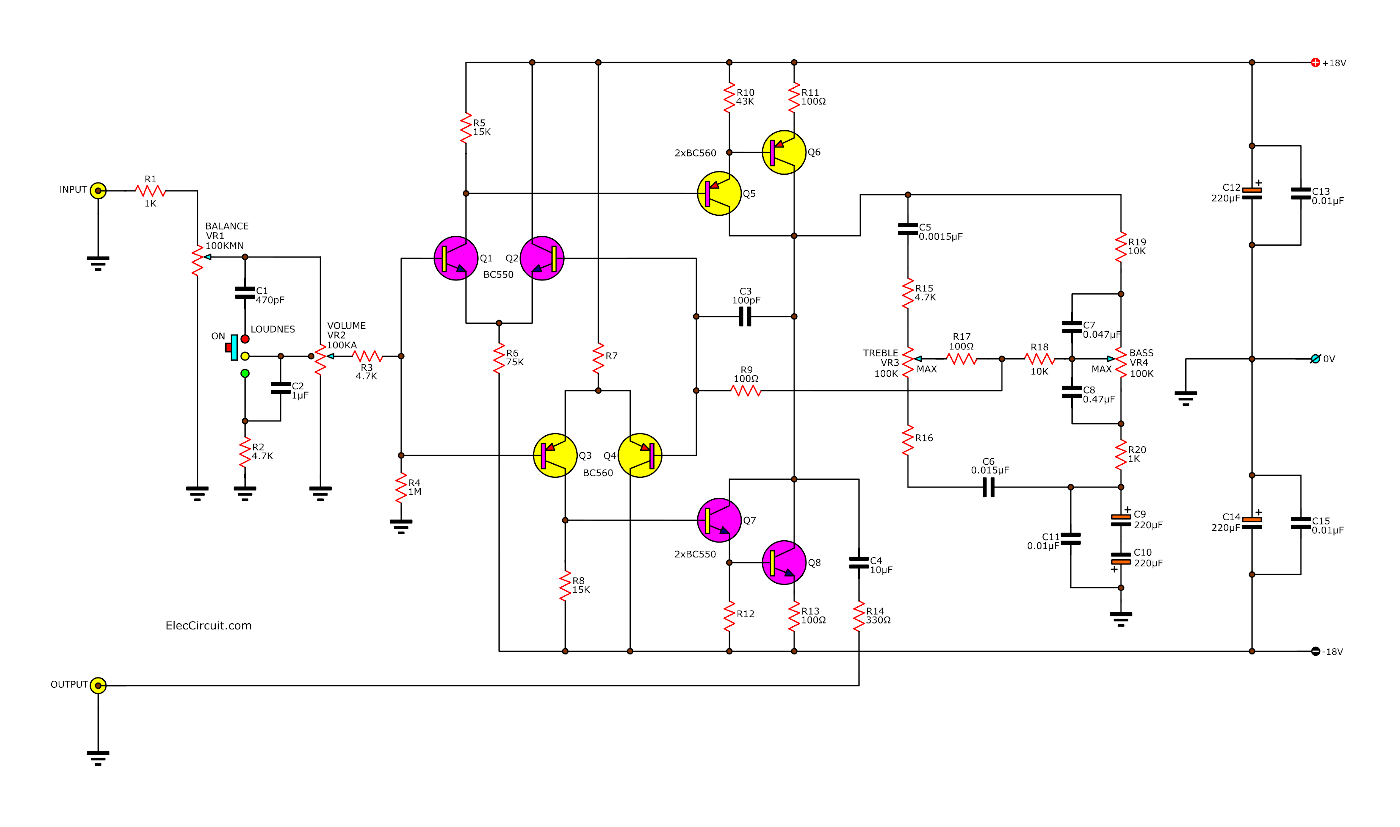
Super digital echo stereo mixer circuit projects
PT2399 Echo Application Circuit DIY Audio Circuits
Super digital echo stereo mixer circuit projects
What is echo cancellation and how does it relate to AV

Digital Echo Circuit PT2399 Electronic Circuit
Analog Delay Line (Echo And Reverb) under Musical

Schematic diagram of ultrasonic Immersion pulseecho
